Wartungsanleitung für die Sturmey-Archer AG Nabe und den Dynohub
Aus WikiPedalia
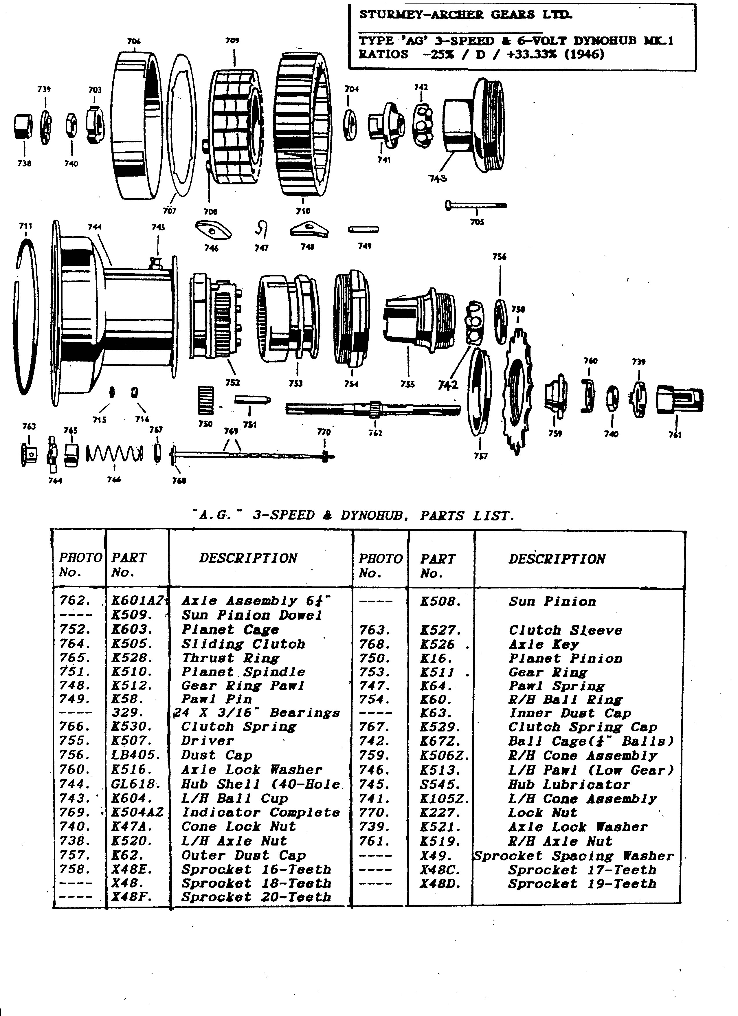
Hier wird eine Wartungsanleitung für die AG Nabe mit integriertem Dynohub wiedergegeben. Weitere Anleitungen kann man der Teileliste und der Explosionszeichnung entnehmen. Es gibt auch einen weiteren Artikel zu Dynohubs.
- Siehe auch

Auseinanderbauen
- Die Schaltkette muss von der Achse geschraubt und entfernt werden. Danach zieht man den Dynohub wie folgt ab:
- Entferne die Dynamokonuskontermutter, die Einstellunterlegscheiben und die Abstandhalter (falls vorhanden). Merke Dir die Reihenfolge, so dass sie beim Zusammenbau wieder in ihrer Originalposition landen.
- Entferne die vier Muttern, die die Magnete halten, die Unterlegscheiben auf der Rückseite des Nabenkörpers und dann entferne die vier Schrauben, die den Magnet fixieren.
- Halte das Laufrad parallel zur Werkbank und klopfe mit einem Werkstatthammer auf das Ende der Welle. Dadurch wird der Dynohub als Einheit herausfallen. Es gibt eine sehr dünne Unterlegscheibe zwischen Konus und der Armatur, die ersetzt werden muss, wenn man die Naben wieder zusammenbaut.
- Der Magnetabstandshalterring kann nun aus dem Nabenkörper gehoben werden.
- Außer es ist absolut notwendig, sollten die Armatur und der Magnet niemals getrennt werden. Wenn man sie dennoch trennen muss, muss man einen Dynohub Keeper Ring benutzen, da der Magnet sonst sehr schnell seinen Megnetismus verliert. Es reicht nur ein kurzer Moment der Trennung, damit der Magnet seinen Magnetismus verliert. Ein Schlüssel, den man quer überden Magnete legen könnte, ist nutzlos gegen den Megnetismusverlust und ist kein Ersatz für den Sturmey Archer Keeper Ring (Diesen Keeper Ring kann man nicht mehr kaufen - daher bitte die Bauteile niemals trennen!).
Sollte man aus irgendeinem Grund dennoch in den Besitz eines Keeper Rings gekommen sein: Um Magnet und Armatur zur trennen halte man die Dynohub Einheit in der linken Hand mit der Abschlussplatte über der Handfläche. Nun setzt man den Keeper Ring über die Armatur. Der Magnet gleitet nun von der Armatur auf den Keeper Ring.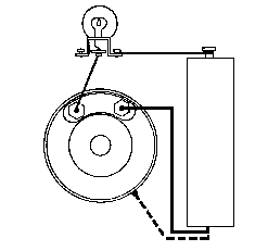
- At this stage it is wise to test the armature with a test meter. If there is no reading on the test meter there is a break in the winding. If a test meter is not available, a battery and bulb may be connected as shown in the diagram, and if the bulb does not light a break in the armature winding is indicated. A second test is to disconnect the lead from one of the armature terminals and touch the outer edges of the armature with the bare lead. If the bulb lights, this indicates a short circuit.
- Unscrew right-hand ball ring from the hub shell and withdraw the gear internals as described in the general instructions.
- Remove the low gear pawls, pins and springs. The pawl pins are easily pushed out of the planet cage to release the pawls and springs.
- Place the left-hand end of the axle in a vise and remove the right hand locknut, washers if any, cone lock washer and cone, making a note of their arrangement so that they can be replaced in their original positions.
- Lift off, in the following order, the clutch spring and cap, the driver, the right-hand ball ring and the gear ring.
- Remove the gear ring pawls, pins and springs. The pawl pins are easily pushed out of the gear ring to release the pawls and springs.
- Pull off the thrust washer and thrust ring.
- Push out the axle key and remove the sliding clutch and sleeve.
- Lift off the planet cage complete.
- Take out the pinion pins and remove the pinions from the planet cage.
- If necessary, because of a worn bearing surface or ratchets, the left-hand ball ring may be removed from the shell by means of special tool (DD10565).

Zusammenbauen
- If the left hand ball cup has been removed from the hub shell, replace it by screwing anti clockwise (it has a left-hand thread).
- Prepare the following subassemblies:
- Fit the ball cage into the driver, with the ring of the ball-retainer facing outwards and the recess in the dust cap also facing outwards. If a new ball retainer is being fitted, the dust cap also should be new. If the sprocket has been removed, see No. 23 below.
- Fit the balls (only 24) and the inner dust cap to the right-hand ball ring, making sure that the balls can revolve freely with the dust cap in place.
- Fit the pawls, pins and springs into the gear ring as described in the general instructions to 'The Re-Assembling of Sturmey Archer Hubs'. (The planet-cage pawls, pins and springs are not fitted at this stage.)
- Smear grease in the channels of the dust cap of the driver and in the recess of the right-hand ball ring. Do not use grease anywhere else.
- Hold the left-hand end of the axle in a vise, so that the slot for the axle key is above the sun pinion, and fit the planet cage.
- Ad the planet pinions and pins. (The small ends of the pins protrude.)
- Fit the sleeve (flange first), the sliding clutch with the recess over the flange of the sleeve and the axle key (with the flat of the key facing upwards), and screw in the indicator rod to hold them in that position.
- Fit the thrust ring and washer, making sure that the flattened ends of the key engage properly in the slots of the thrust ring. [These parts are combined into one in later production.]
- Fit the previously prepared gear ring sub-assembly.
- Fit the previously prepared right-hand ball-ring sub-assembly.
- Fit the previously prepared driver sub-assembly.
- Drop the clutch spring over the axle.
- Fit the cap and screw up the right-hand cone finger-tight. Then Loosen it back half a turn and lock it in that position with the special washer and locknut. On no account must the cone be unscrewed more than half a turn, as that would throw the gear mechanism out of adjustment.
- Invert the assembly in the vise and pour about two teaspoonfuls of good quality thin oil into the planet cage, then fit the planet cage pawls as described in the general instructions to 'The Re-assembling of Sturmey-Archer Hubs'.
- Screw up the left-hand cone.
- If the magnet and armature have been separated, take the magnet and keeper ring in the left hand and, with the right hand, lay the armature alongside it.
- While holding the magnet with the chamfer facing outwards, push the armature and the keeper through so that the magnet slides from the keeper on to the armature
- Fit the card disc (carrying patent numbers) inside the cover plate, with its notches opposite the magnet notches.
- Fit the cover plate over the magnet, chamfer inwards, making sure that the four holes in the cover plate are in line with the notches in the card and the magnet.
- Fit the metal spacing ring into the hub shell.
- Fit the shim washer.
- Push the complete dynamo unit into the hub shell, making sure that the holes in the cover plate are in line with those in the hub shell.
- Fit the magnet fixing screws, washers and nuts.
- Fit the spacing washers, adjusting washers and dynamo cone lock nut in arrangement noted when dismantling. Check wheel adjustment.
- If the sprocket has been removed from the driver, fit the outer dust cap over the driver before replacing the sprocket, and see that the dust cap is properly centerd on the flange of the driver. Replace the sprocket and spacing washers in the arrangement noted when dismantling, and add the circlip.
- Replace the wheel in the cycle frame and adjust the gear as described in 'The Installation and Adjustment of Sturmey-Archer Hubs.'
Werbung:
Siehe auch
Quelle
Dieser Artikel basiert auf dem Artikel Servicing the Sturmey-Archer AG Hub and Dynohub von der Website Sheldon Browns. Originalautor des Artikels ist Sheldon Brown.
Weitere interessante Artikel zum Thema Sturmey-Archer
- S3X
- Die Sturmey-Archer ASC Fixed Gear Drei-Gang-Nabe
- Sturmey-Archer Naben
- Fehlersuche bei der Sturmey-Archer Sprinter Fünf-Gang-Nabe
- Die Sturmey-Archer Sprinter Fünf-Gang-Nabe
- Sturmey-Archer SW Drei-Gang-Naben
- Die Sturmey-Archer ASC Fixed Gear Drei-Gang-Nabe/Wartung der Sturmey-Archer ASC Fixed Gear Drei-Gang-Nabe
- Quadrant Shifter
- Dynohub
- SunRace
Weitere interessante Artikel zum Thema Nabenschaltung
Weitere interessante Artikel zum Thema Licht
Weitere interessante Artikel zum Thema Workshop
Weitere interessante Artikel zum Thema Sheldon Brown
- Sattelstützenmaße
- Ritzelabstände (Tabelle)
- Auswechselbarkeit von Vierkant-Kurbelaufnahmesystemen bei Innenlagern
- Kettenlinienstandards (Tabelle)
- Ein bequemer Sattel
- Nabenbreiten (Tabelle)
- Alles über Nabenschaltungen
- Shimano Nexus und Alfine Acht-Gang-Naben
- Reifengrößen
- Gute und schlechte Schnellspanner